Vertex Shaders
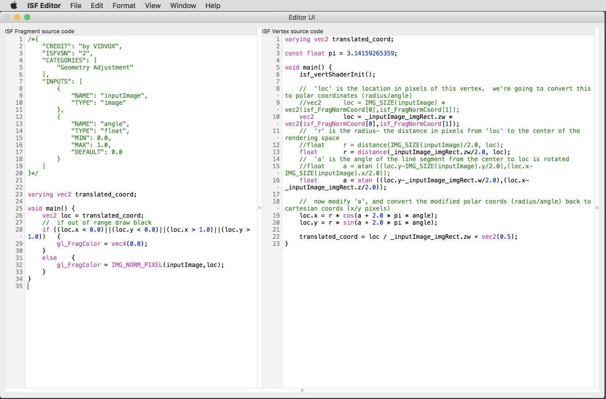 Editing Vertex Shader in the ISF Editor.
 When writing shaders that are designed for 2D images as the ISF specification is currently designed for, typically most of the code you'll write is in the fragment shader (.fs) of your ISF shader. In all of the examples we've seen so far we haven't had to create a vertex shader at all - part of the ISF specification is to automatically generate one if there isn't one provided.
In this chapter we'll look at how to add a custom vertex shader to work alongside a fragment shader with ISF and one of the simple cases where they can be useful. The specific topics covered will be:
- What are vertex shaders and how are they different from fragment shaders?
- How to include a vertex shader as part of an ISF composition.
- How to pass information from a vertex shader to a fragment shader using varying variables.
- A brief introduction to polar vs Cartesian coordinate spaces.
- Using a vertex shader to create a basic rotation effect.
Vertex Shaders vs Fragment Shaders
Though ISF is designed to work with images, within OpenGL an image is a 2D plane, where this 2D plane itself has 4 coordinates (vertices) that make up its position in space and has pixels (fragments) on it.
The OpenGL Shading Language provides different types of shaders, vertex and fragment, for manipulating both the coordinate points and the pixels respectively. If you are only looking to create or manipulate the pixels of an image, very often the fragment shader alone is enough because you want to draw using whatever 2D geometry is provided by the rendering pipeline that your generator or filter is running inside of.
However there are a few cases where it can be beneficial to include a custom vertex shader. One such example that we will look at in this chapter is applying a rotation filter, which manipulates the coordinate points directly, moving the entire plane by adjusting the 4 vertex points instead of every single pixel. Another use case that we will look at in the next chapter is using a vertex shader to precompute fragment coordinates for when performing convolutions.
Note: In GLSL there are even more kinds of shaders. Currently ISF is made for working with 2D images and only makes use of vertex and fragment shaders. A draft version of the next version of the ISF specification introduces additional conventions for working with 3D shapes with vertex and geometry shaders.
Using Vertex Shaders in ISF
When including a vertex shader as part of an ISF composition, start by creating a basic fragment shader that will include the JSON blob. Then create another file with the same name but use a 'vs' file extension. Whenever a host application tries to load the fragment shader, it will look to see if a custom matching .vs is included. If not, the default vertex shader is used instead.
The most basic vertex shader for ISF would look something like this:
//	passthru.vs
//	put your code in the main() {} function

varying vec2 translated_coord;

void main()
{
	//	make sure to call this in your custom ISF shaders to perform initial setup!
	isf_vertShaderInit();
	translated_coord = isf_FragNormCoord;
}
And it match up with a corresponding boring passthru.fs that looks like this:
//	passthru.fs
/*{
	"DESCRIPTION": "Passes through each pixel",
	"CREDIT": "by VIDVOX",
	"ISFVSN": "2",
	"CATEGORIES": [
		"TEST-GLSL FX"
	],
	"INPUTS": [
		{
			"NAME": "inputImage",
			"TYPE": "image"
		}
	]
}*/

varying vec2 translated_coord;

void main() {
	//	uses the translated_coord provided from the .vs
	gl_FragColor = IMG_NORM_PIXEL(inputImage,translated_coord);
}
This vertex shader isn't particularly exciting and is essentially what the default .vs looks like if you do not include a custom one. Like the fragment shader, it just passes through whatever vertex information is passed into it. The one important detail here is the isf_vertShaderInit(); which must be called to do the initial setup for the vertex shader.
The other noteworthy addition to this code is:
varying vec2 translated_coord;
Which is found in both the .vs and .fs files. This is a special variable type know as varying.
Varying and Uniform Variables in Vertex Shaders
When including a custom vertex shaders, there are a few special kinds of variables that can be used to communicate between the different shaders.
We've already learned how uniform variables are used to pass information from the host application into our shaders and in ISF these variables are defined as part of the JSON blob. Any uniforms declared in the JSON blob are also automatically available to the fragment shader.
The varying variable type makes it possible to use the vertex shader to precompute values that are passed into the fragment shader, interpolating along the primitive in the process. These
Note: Though the `varying` variable type is currently supported, future versions of GLSL have deprecated this idea. As such it may get phased out in future versions of ISF. However, most ISF hosts aim to be backwards compatible and this is exactly why the "ISFVSN" tag is included as an attribute in the JSON blob.
Creating a Rotation Filter
One of the practical use cases for working with vertex shaders in 2D space is creating a rotation filter.
In this section we'll write our rotation filter in two different ways, both essentially based on the same mathematical operations. The first method will be written entirely in a fragment shader and the second will make use of the custom vertex shader.
This is also a great opportunity to talk a bit about with angles, trigonometry and polar coordinate spaces, which are extremely useful when writing shaders.
Angles, Trigonometry and Polar Coordinate Spaces
So far when writing our shaders we've dealt exclusively with 2D points in the form of (x, y). In some cases those values were normalized (ranged 0.0 to 1.0) and at other times they were ranged, going between 0.0 and and maximum value like the RENDERSIZE.
Another useful way to represent this information is in polar coordinates, where instead of (x, y) values, each point is represented by a distance and an angle (r, θ). Once a coordinate is in the (r, θ) form, you can make adjustments to its position by adjusting the distance or angle, which is ideal for performing rotations, bump distortions and other visual effects that happen radially or in a circular fashion.
Converting to and from polar coordinates and traditional Cartesian coordinate spaces is easy, as you will see in the rotation filter code below.
GLSL provides many built-in functions for working with angles and trigonometry, a list of which can be found in the ISF and GLSL Variables and Uniforms Reference Page for quick lookup.
Rotation in a Fragment Shader
If we were limited to working with a fragment shader, as some environments are, the following code is sufficient for rotating an image.
Here a rotation is performed by converting each point to polar coordinates, adding to the angle and then converting back to Cartesian for the look up from the original image.
This same math for going between coordinate spaces can be re-used in other situations. Though not exactly the same, you may recall seeing similar looking code in Chapter 3 when we looked at the Twirl.fs filter.
Rotation in Fragment Shader.fs
/*
{
  "CATEGORIES" : [
    "Geometry Adjustment"
  ],
  "ISFVSN" : "2",
  "INPUTS" : [
    {
      "NAME" : "inputImage",
      "TYPE" : "image"
    },
    {
      "NAME" : "angle",
      "TYPE" : "float",
      "MAX" : 1,
      "DEFAULT" : 0,
      "MIN" : 0
    }
  ],
  "CREDIT" : "by VIDVOX"
}
*/

const float pi = 3.14159265359;

void main()	{
	//	'loc' is the location in pixels of this vertex.  we're going to convert this to polar coordinates (radius/angle)
	vec2		loc = IMG_SIZE(inputImage) * vec2(isf_FragNormCoord[0],isf_FragNormCoord[1]);
	//	'r' is the radius- the distance in pixels from 'loc' to the center of the rendering space
	float		r = distance(IMG_SIZE(inputImage)/2.0, loc);
	//	'a' is the angle of the line segment from the center to loc is rotated
	float		a = atan ((loc.y-IMG_SIZE(inputImage).y/2.0),(loc.x-IMG_SIZE(inputImage).x/2.0));

	//	now modify 'a', and convert the modified polar coords (radius/angle) back to cartesian coords (x/y pixels)
	loc.x = r * cos(a + 2.0 * pi * angle);
	loc.y = r * sin(a + 2.0 * pi * angle);

	loc = loc / IMG_SIZE(inputImage) + vec2(0.5);
	if ((loc.x < 0.0)||(loc.y < 0.0)||(loc.x > 1.0)||(loc.y > 1.0))	{
		gl_FragColor = vec4(0.0);
	}
	else	{
		gl_FragColor = IMG_NORM_PIXEL(inputImage,loc);
	}
}
Rotation in a Vertex Shader
Now let's do the same thing, but instead of doing the translation in the fragment shader we'll use the vertex shader
Here is the code for Rotate.vs / Rotate.fs
//	Rotate.vs
varying vec2 translated_coord;

const float pi = 3.14159265359;

void main()	{
	isf_vertShaderInit();

	//	'loc' is the location in pixels of this vertex.  we're going to convert this to polar coordinates (radius/angle)
	vec2		loc = IMG_SIZE(inputImage) * vec2(isf_FragNormCoord[0],isf_FragNormCoord[1]);
	//	'r' is the radius- the distance in pixels from 'loc' to the center of the rendering space
	float		r = distance(IMG_SIZE(inputImage)/2.0, loc);
	//	'a' is the angle of the line segment from the center to loc is rotated
	float		a = atan ((loc.y-IMG_SIZE(inputImage).y/2.0),(loc.x-IMG_SIZE(inputImage).x/2.0));

	//	now modify 'a', and convert the modified polar coords (radius/angle) back to cartesian coords (x/y pixels)
	loc.x = r * cos(a + 2.0 * pi * angle);
	loc.y = r * sin(a + 2.0 * pi * angle);

	translated_coord = loc / IMG_SIZE(inputImage) + vec2(0.5);
}
And the matching Rotate.fs:
/*{
	"CREDIT": "by VIDVOX",
	"ISFVSN": "2",
	"CATEGORIES": [
		"Geometry Adjustment"
	],
	"INPUTS": [
		{
			"NAME": "inputImage",
			"TYPE": "image"
		},
		{
			"NAME": "angle",
			"TYPE": "float",
			"MIN": 0.0,
			"MAX": 1.0,
			"DEFAULT": 0.0
		}
	]
}*/

//	Rotate.fs

varying vec2 translated_coord;

void main() {
	vec2 loc = translated_coord;
	//	if out of range draw black
	if ((loc.x < 0.0)||(loc.y < 0.0)||(loc.x > 1.0)||(loc.y > 1.0))	{
		gl_FragColor = vec4(0.0);
	}
	else	{
		gl_FragColor = IMG_NORM_PIXEL(inputImage,loc);
	}
}
As you may note, the code here looks very much the same as in the previous example. However because we've moved a lot of the computation over to the vertex shader, this version will run more efficiently.
The fragment shader here still does the small amount of work to make sure that the translated_coord is within the readable range for the original image and if not returns transparent black instead.
Other Vertex Shader Use Cases
Over the next few chapters we will see a handful of other examples where vertex shaders come into play, particularly with the concept of Convolution which we will investigate in the next chapter.